Load Specifications
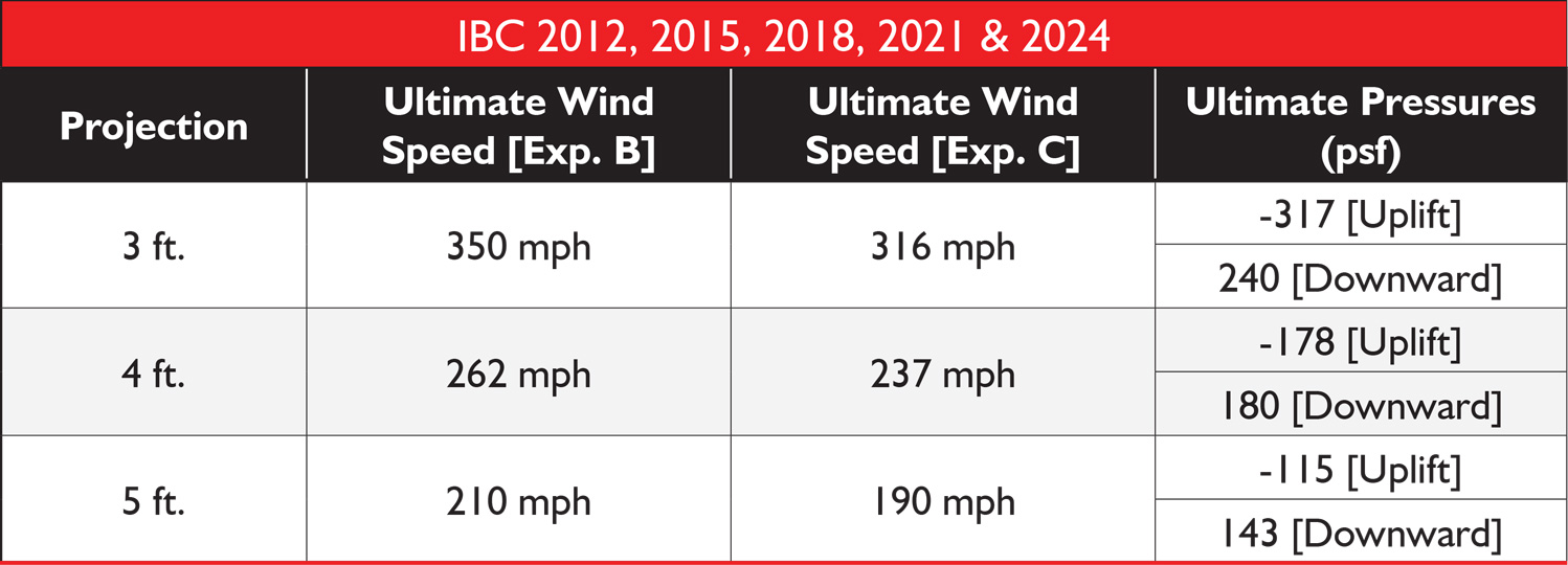
Wind loads shown are uniform loads on a 4′- 6″ wide canopy with 2 braces.
Wind loads calculated per ASCE 7-16 Section 30.11, using net pressure coefficients on attached canopies considering contributions from upper and lower surfaces.
- Topographic factor, Kzt = 1.0
- Wind directionality factor, Kd = 0.85
- Ground elevation factor, Ke = 1.0
- Net pressure coefficient, GCp = -1.4 for Uplift pressure & +0.9 for Downward pressure
- Velocity pressure coefficient, Kz = 0.85 for Exposure – B & 1.04 for Exposure – C
- Mean building eave height, he:
- Max 60′ above ground for Exposure – B
- Max 40’ above ground for Exposure – C

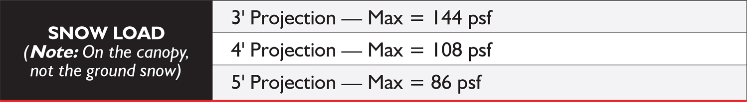
Snow loads shown are uniform loads on a 4′-6″ wide canopy with 2 braces. Snow loads shall be determined by engineer utilizing applicable codes and project-specific design criteria.
NOTE: Wider canopies, more stringent loading requirements and customer engineering analysis available.
Use our Canopy Calculator to generate specifications based on load data, building codes, risk categories and building dimensions.
Construction
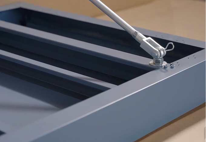
- 5/8″ dia. rod end 4140 hot rolled annealed (HRA) [F.y = 125 ksi]
- 16-gauge telescoping support channels mount behind wall panel between girts, mounting clips and fasteners included
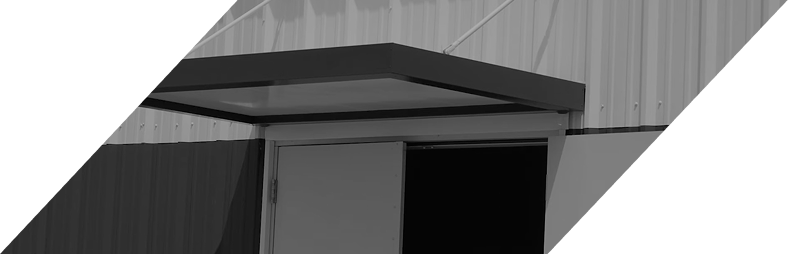
- Economical and attractive overhead protection from the elements
- Specifically designed for high wind load and heavy snow load areas
- 24-gauge flat soffit and integral gutter with rear-mounted drains
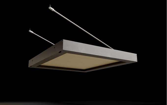
- 16-gauge galvanized internal frame for 3’ and 4’ projections, and 14-gauge galvanized internal frame for 5’ projection
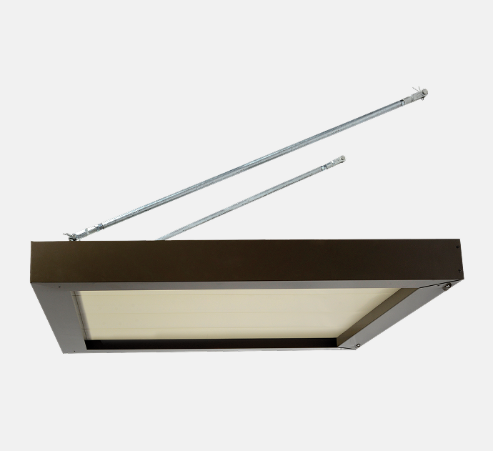
- 3/4″ dia. galvanized pipe hangers with adjustable rod ends
Finishes
- Galvalume steel
- Silicone polyester, Kynar® and powder coated finish options available in a wide range of colors
- Custom color matching
- Single color or two-tone (contrasting gutter/fascia and soffit)
Options
- Masonry mount (anchors by others)
- Downspouts
- Front mounted drains
- Light Kit (see Lighted Door Canopies)